
Range Calc Mode is the quickest way to turn a visual traffic picture into a measurable one. Instead of estimating spacing from the map alone, you can select aircraft and read distance, bearing, and altitude difference directly on the workspace.
Use this guide after AO Guide: Reading Target Details. It assumes you can already search for an aircraft, select a target, and read the basic target fields.
In this guide, you will learn how to:
- enable
Range Calculator - select two aircraft for a clean measurement
- read nautical miles, bearing, and vertical difference
- extend a measurement across three selected targets
- keep the map readable when traffic is dense
Step 1. Enable Range Calculator
Open the main menu, then choose Tools and enable Range Calculator.
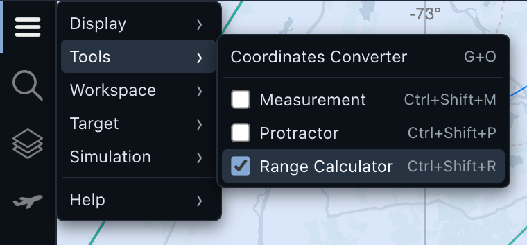
When Range Calculator is active, AO shows Range Calc Mode on the map. This tells you that aircraft selection now creates measurement geometry instead of only opening one target for inspection.
Use the keyboard shortcut shown in the menu when you want to toggle the tool quickly.
Step 2. Start with two targets
For the first measurement, choose two aircraft that are close enough to compare but far enough apart that the labels do not collide.
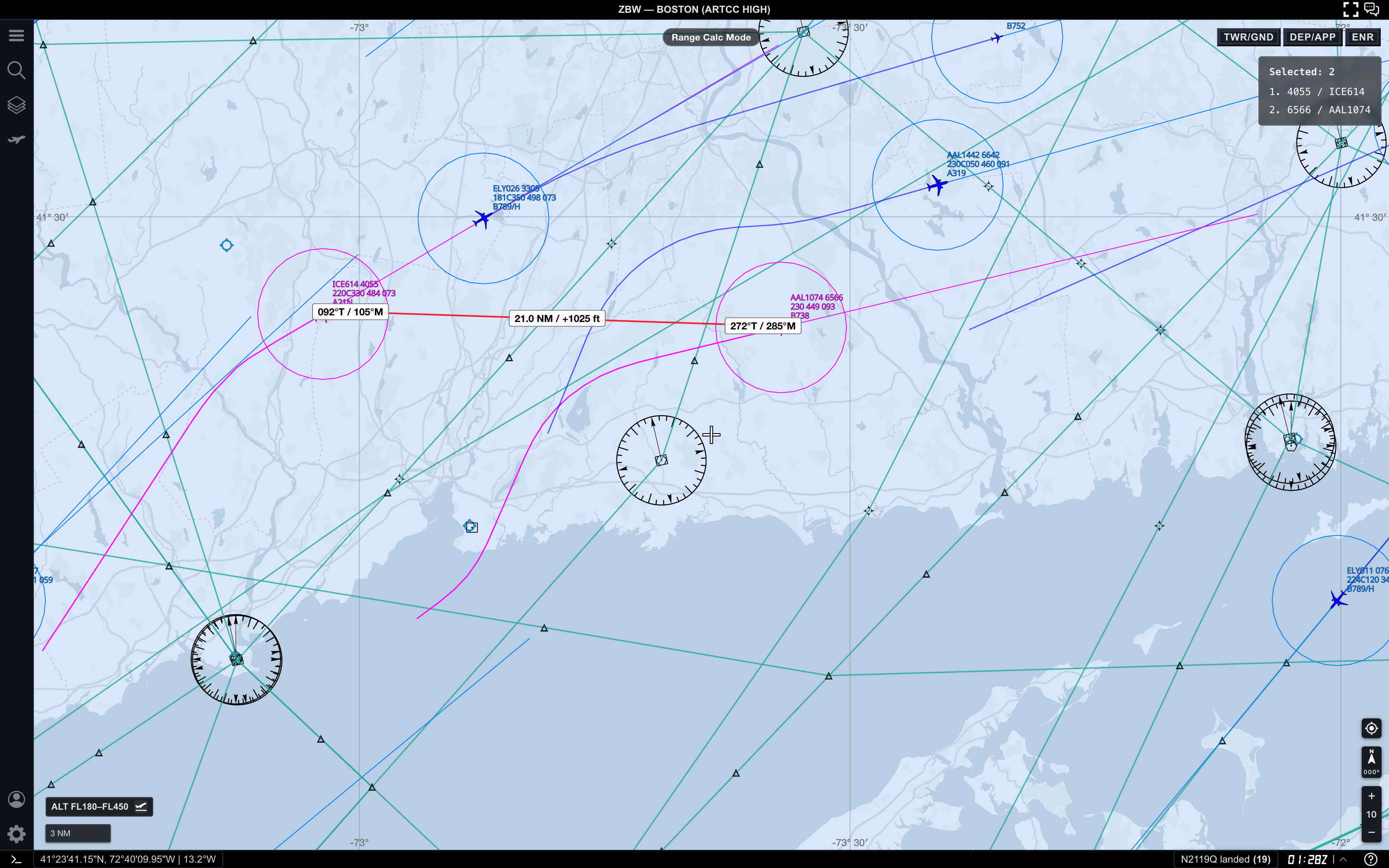
In this example, AO shows:
Selected: 2in the upper-right list- a red measurement line between the selected aircraft
- bearing labels near each aircraft
- a center label with distance and altitude difference
The center label reads 21.0 NM / +1025 ft. The first value is the distance in nautical miles. The second value is the vertical difference between the two selected aircraft, using the selected order.
Positive and negative signs are directional. AO compares the next selected aircraft against the previous selected aircraft. If you select the same pair in the opposite order, the distance is the same, but the altitude sign can reverse.
Step 3. Read the bearing labels
Range Calc Mode also adds direction labels near the endpoints.
Each endpoint label shows:
- true bearing, marked with
T - magnetic bearing, marked with
M
Use the center label when you care about spacing. Use the endpoint bearing labels when you want to understand the direction from one selected target to the next.
For a quick traffic check, distance and vertical difference usually matter first. Bearings become more useful when you are comparing flows, intercepts, or relative geometry.
Step 4. Add a third selected aircraft
You can select more than two aircraft. AO connects them in selection order.
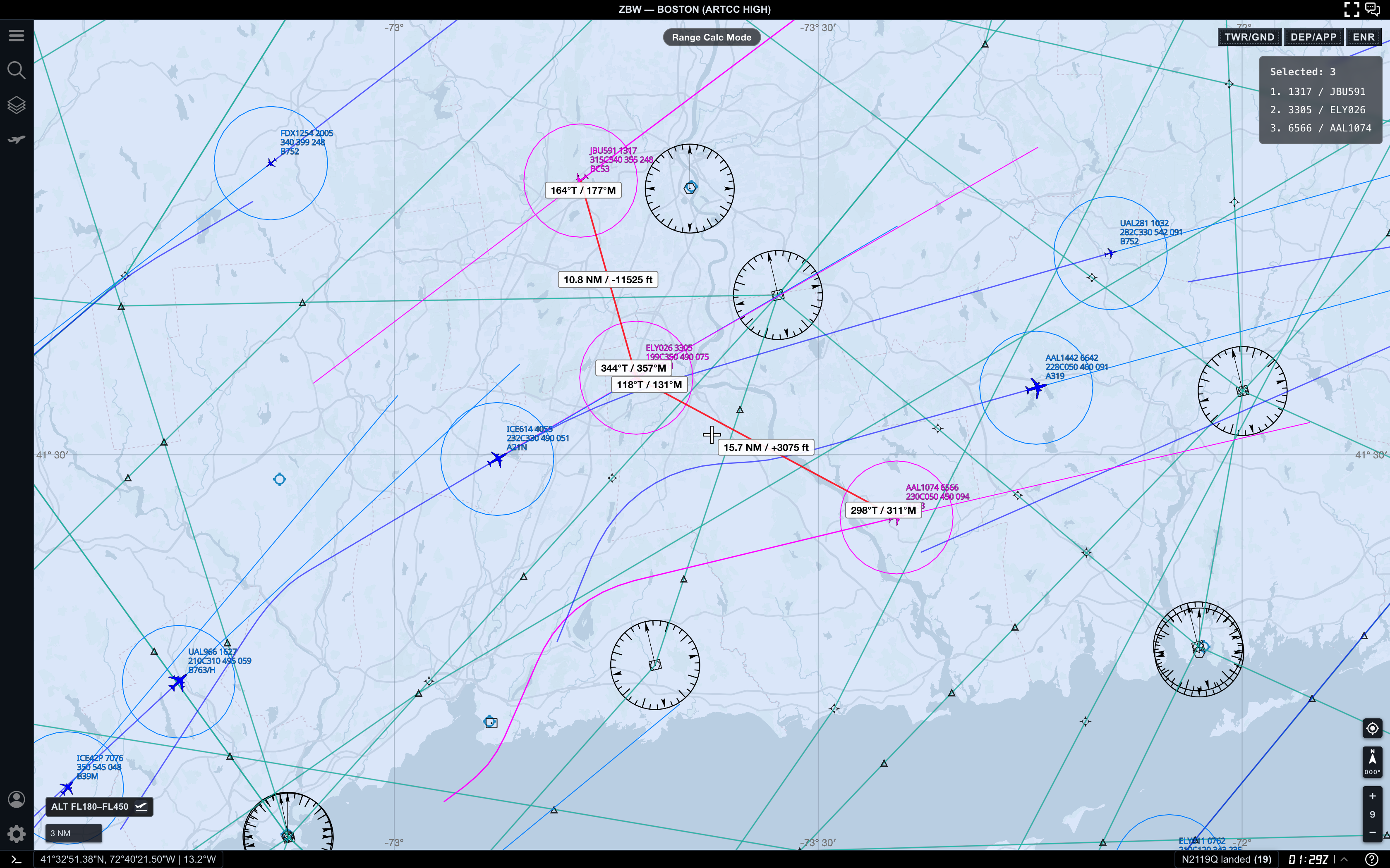
With three selected targets, AO measures:
- target 1 to target 2
- target 2 to target 3
It does not draw every possible pair. This keeps the map easier to read and makes the measurement sequence predictable.
Use this when you want to compare spacing along a flow or understand how one middle target relates to aircraft ahead and behind it.
Step 5. Keep the measurement readable
Range Calc Mode is most useful when the map is already controlled. If the screen is too dense, the measurement labels compete with aircraft labels, routes, fixes, and range rings.
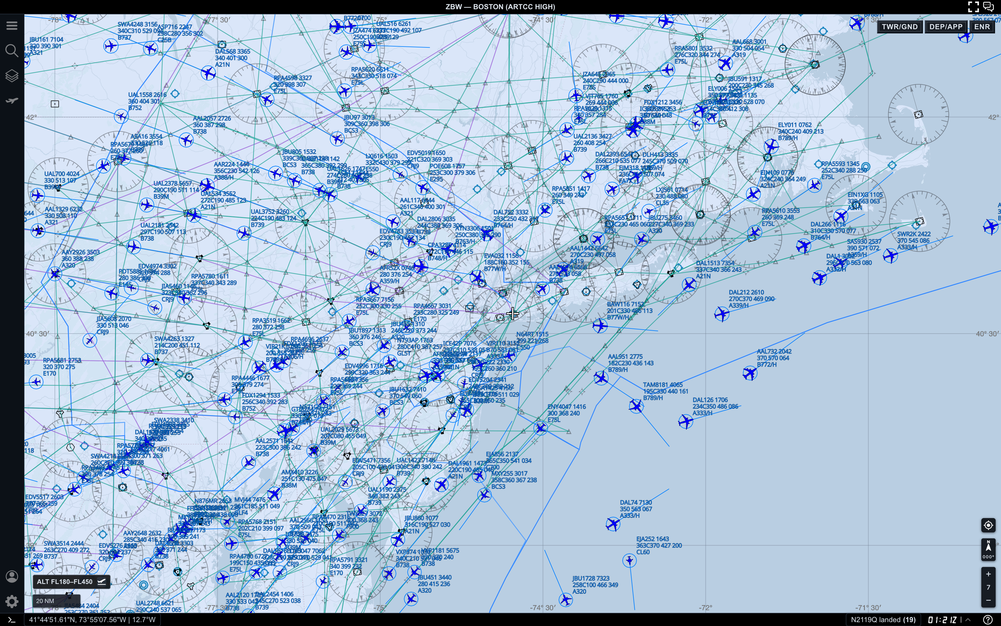
Before measuring in a busy area:
- zoom in until the selected aircraft have space around their labels
- adjust the altitude filter so irrelevant traffic disappears
- select fewer targets
- clear the measurement and rebuild it in a cleaner order
- use
DEP/APPorENRdepending on the traffic you are comparing
A clean two-target measurement is usually more useful than a crowded multi-target measurement.
Practical reading order
When you use Range Calc Mode, read the map in this order:
- Confirm
Range Calc Modeis active. - Check the
Selectedlist so you know which targets are being measured. - Read the center label for distance and vertical difference.
- Read the endpoint bearing labels only if direction matters.
- Compare the measurement with the target labels and surrounding traffic.
This keeps the measurement tied to the actual aircraft, not just the red line.
Common mistakes
- Selecting too many aircraft before understanding the first line
- Reading the altitude sign without checking selection order
- Measuring in a dense map view where labels overlap
- Forgetting that AO connects selected targets sequentially
- Leaving Range Calculator on after finishing a measurement workflow
Next step
After you can measure traffic spacing clearly, continue with AO Guide: Following an Aircraft with Follow Target to keep one selected aircraft centered while the map updates around it.